What’s New in TopSolid’Wood v6.26
User interface
Simplified access to TopSolid’Learning and TopSolid’Faq
TopSolid’Learning is now directly accessible from the home page.

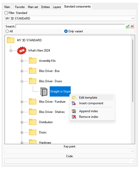
Opening a component from the tree
You can now edit a component model by right-clicking on the corresponding node in the standard component tree.
New “Construction volumes” section in Entities tree
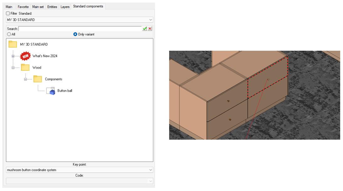
When a component with at least one driver is included via the tree, the Same component button becomes available. This feature allows for quick and easy re-inclusion of the same component.
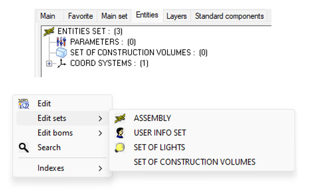
New “Construction volumes” section in Entities tree
The Set of construction volumes section is now visible in the Entities tree when a new document is created.
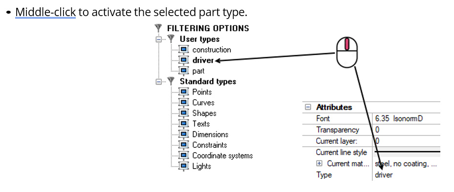
Purging the current part type
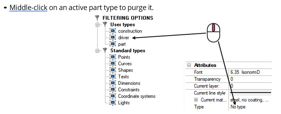
New middle-click actions in the Filtering options tab offer improved management of the current part type:
Driver merging
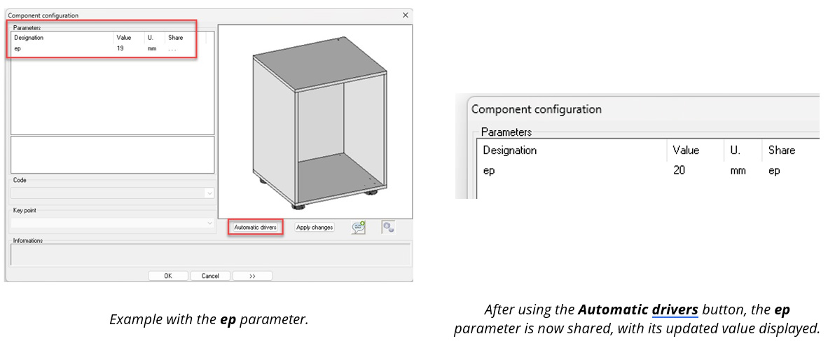
When including a component with drivers, the Automatic drivers button now merges the component parameters with those already present in the inclusion document.
For example, when including a cabinet with a driver parameter named identically to an existing parameter in the document, using the Automatic drivers button automatically connects the cabinet driver to the inclusion document’s driver.
Using predefined designations and references
It is now possible to access predefined designations and references set in Tools > Options.

Design
Orientation angle between the part’s sawing-up coordinate system and the nesting support
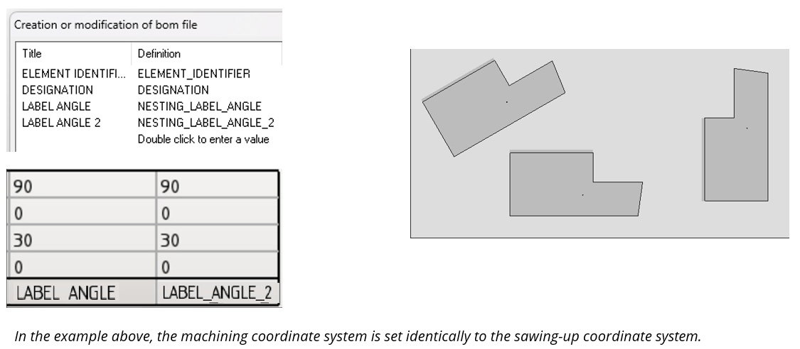
A new BOM property, NESTING_LABEL_ANGLE_2, indicates the value of the angle between the nesting support and the part’s sawing-up coordinate system.
New button for serial copy
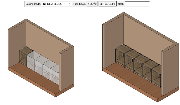
When a driver block component is included in the result of a distribution, the Serial copy button is now automatically proposed.
Horizontal distribution
This new command allows you to include a new standard component and immediately launch horizontal distribution.
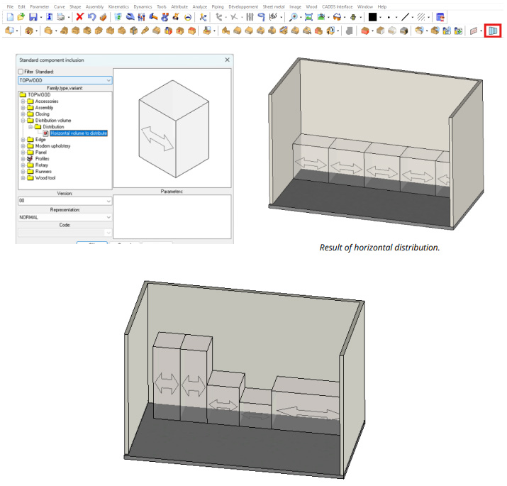
Result of horizontal distribution after modifying the parameters of the distributed component
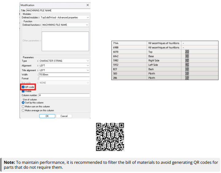
QR code in bills of materials
A new feature allows you to convert a BOM property into a QR code for a designated column. To activate it, check the QR code option when editing the relevant column.
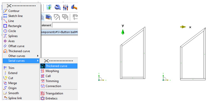
New cutting mode for thickened serial curves
A new cutting mode is available when using the Thickened curve command in serial mode.
Perpendicular cuts are generated between two perpendicular curves, along the given direction. If this is not the case, miter cuts are generated.
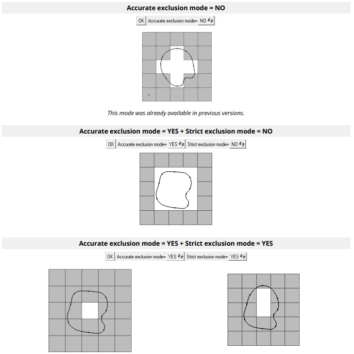
Closed curve exclusion
When excluding instances from a propagation by a closed curve, two exclusion modes, accurate and strict, are now available.
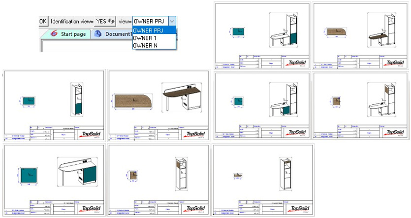
Highlighting a part in multi-drawings
When creating a multi-drawing template, new view creation options are available. For example, they can be used to highlight a specific part within its subassembly, making it easier to visualise.
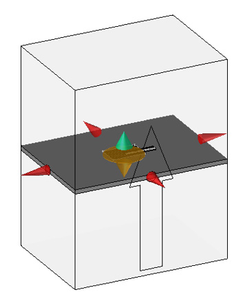
Editing arrows added after creating a constrained block or section
It is now possible to use edit arrows after creating a constrained section or block in manual mode.
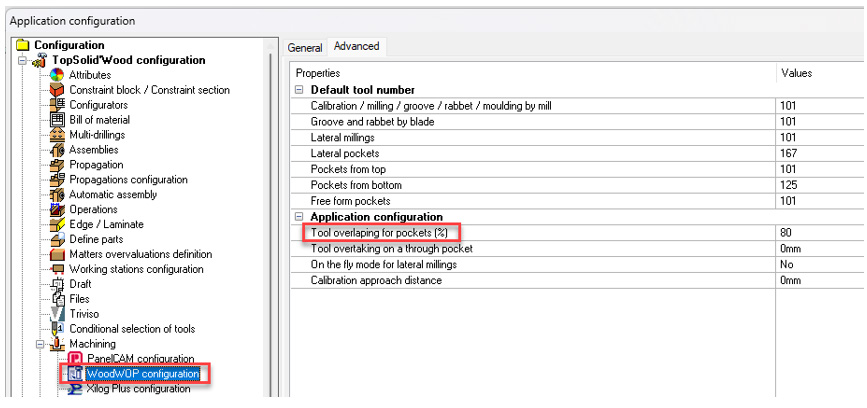
WoodWOP interface
Tool overlap for pockets
The tool overlap property now applies to both through pockets and blind pockets. The associated configuration word is: ZX_ZWOO_CAM_MPR_THROUGH_POC_ADVANCE (default value: 80%)
Cutting and Punching
Improved delete command
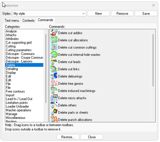
Previously, the Delete command displayed the different types of entities to delete in a drop-down list
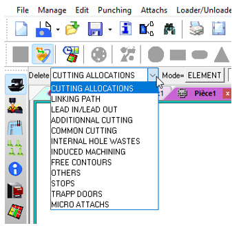
Each entity type now has its own dedicated delete command. This enhancement lets you configure a customized menu containing one or more specific delete commands, all grouped together under the Delete category.
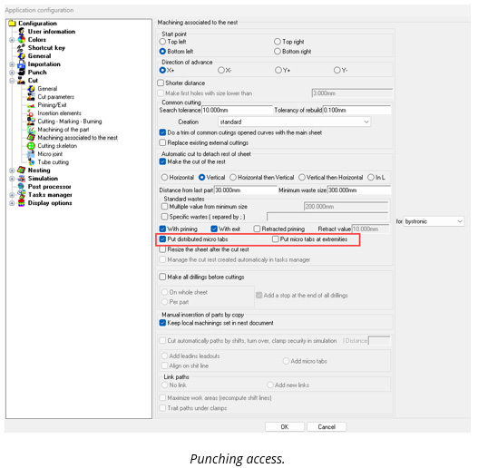
Micro-tabs at the ends of waste cuts
In previous versions, micro-tabs for waste cuts were only available in distributed mode.
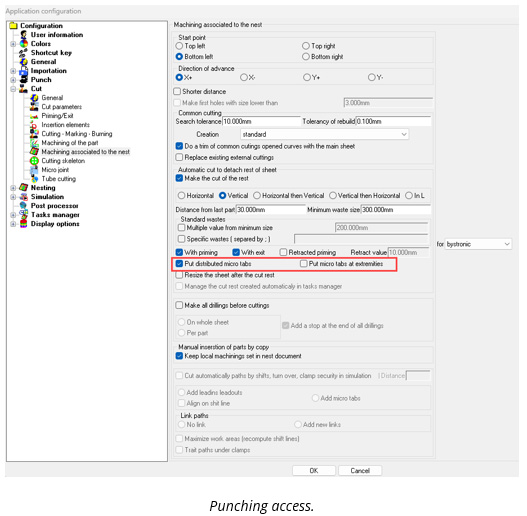
Micro-tabs can now be added to the ends of waste cuts. This feature is available for both punching and cutting.
In punching, default attachment tools can also be placed.
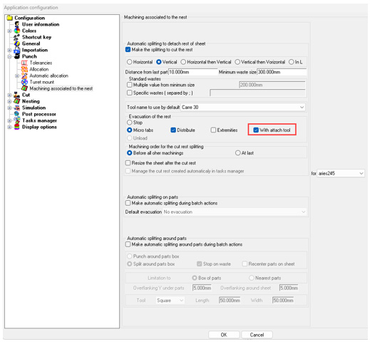
Punching
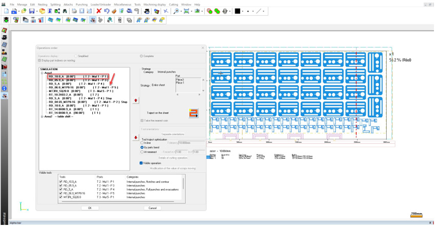
Improved tool reordering in operation sequence
The management of tools in the operation order dialog box has been simplified with the ability to reorder tools using drag-and-drop.
Only one line can be moved at a time.
Punch point management for triangle tools
The management of right-angled isosceles triangle tools has been optimized with a new feature that lets you define the exact punch point. You can now position the center point by specifying offsets on the X and Y axes from the point on the vertical line.
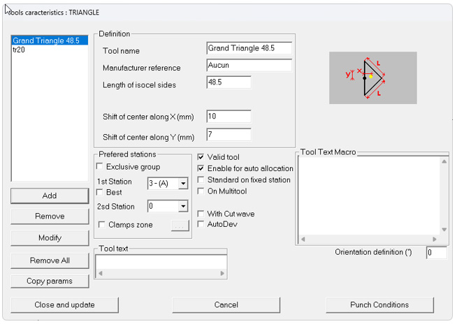
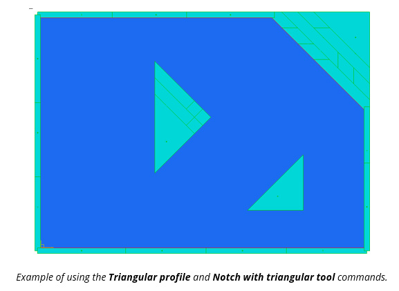
This enhancement simplifies the use of triangle tools and eliminates the need to create special tools.
Improved stop position for splitting around parts
The Border line command, with the Split around parts box option, has been optimized. Enhancements include automatic deletion of unnecessary lines and the ability to add one or more stops as needed.
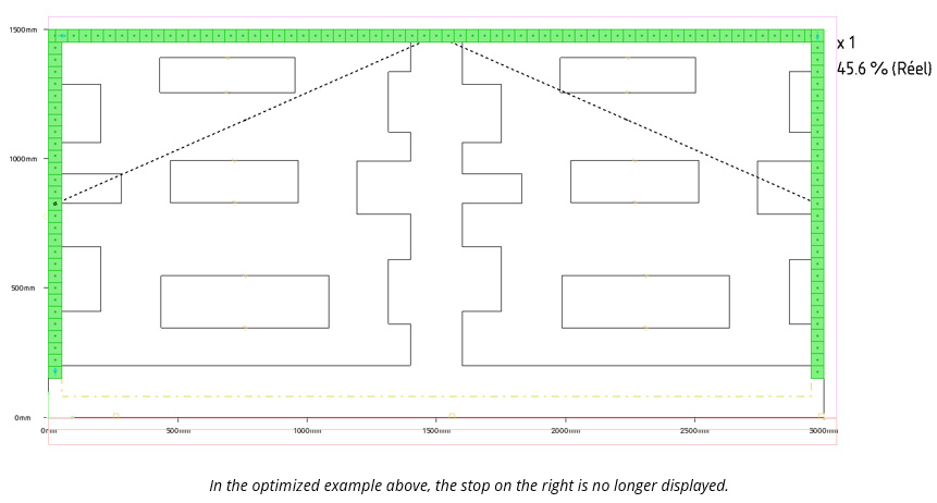
Optimised splitting around parts command
A new feature has been added to the Border line command, when the Split around parts box option is selected.
Previously, splitting was only calculated relative to the bounding box of the parts, with automatic overflanking based on the tool dimensions.
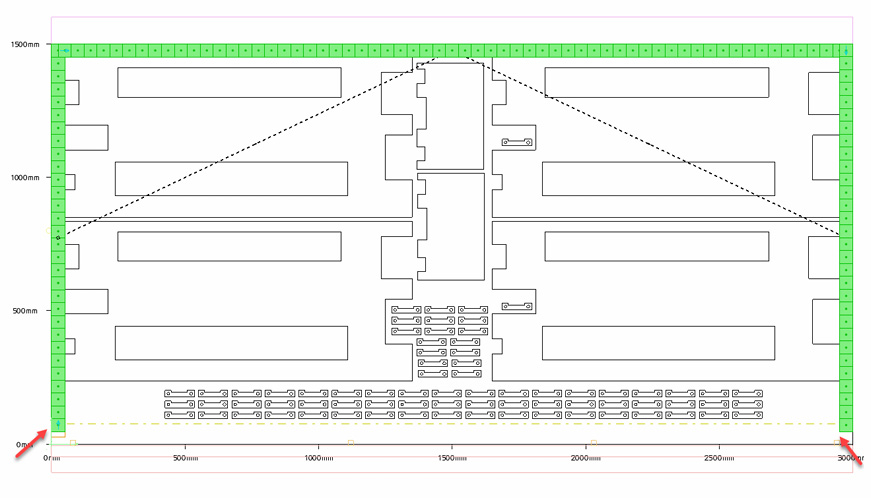
On some machines, small clamps are used to evacuate the skeleton in clamps, leaving an unpunched area. Previously, it was necessary to adjust the splitting line to allow this operation.
You can now choose whether splitting operations are calculated based on the parts’ bounding box or in relation to the parts close to these splitting operations (for left and right edges).
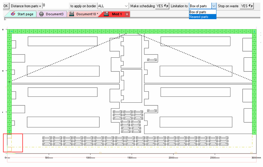
Optimised sheet splitting based on waste size
When using the Border line command with the Split around parts box option, a machine stop could be generated if the left margin was too large in relation to the width of the tool used for splitting.
Stops can now be avoided by splitting only the top horizontal and right vertical sections.
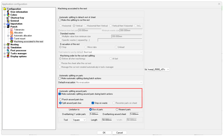
An additional option allows parts to be recentered on the sheet when the left and right margins can be split in a single pass, optimizing the process.
For automatic splitting around parts during associated nesting actions, you can configure the Stop on waste and
Recenter parts on sheet options in Tools > Options > Machining associated to the nest.
Sucker check alert
A new alert has been added to the simulation phase. It triggers if unloading is programmed for a part but no sucker has been assigned, and the part has not been placed on a pallet.

Message Us
Get In touch. Ask Any Questions or Get a Free Demo
Call Us
(02) 7205 4820
Contact us
Opticad Solutions Pty Ltd
Kareela, New South Wales, Australia
Phone : 02 7205 4820
